Hybrid High Frequency Printed Circuit Boards 3-Layer Hybrid RF PCB Made On 13.3mil RO4350B and 31mil RT/Duroid 5880
(PCBs are custom-made products, the picture and parameters shown are just for reference)
Introduction
Hello Everyone,
Warm greetings!
Today, we will discuss hybrid PCBs, which can consist of a combination of FR-4 and high-frequency materials, or a blend of different high-frequency materials with varying dielectric constants (DK), such as RT/Duroid 5880 and RO4350B.
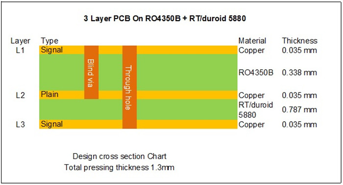
This article focuses on a specific type of mixed high-frequency PCB constructed from 13.3mil (0.338mm) RO4350B and 31mil (0.787mm) RT/Duroid 5880, designed for multi-coupler antenna applications.
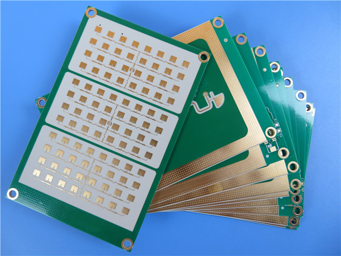
This is a 3-layer board that one layer is etched off.
Basic Specifications:
| Basic Specifications | Description |
|---|---|
| Base Material | RO4350B 13.3mil (0.338mm) + RT/Duroid 5880 31mil (0.787mm) |
| Dielectric Constant | 3.48 ± 0.05 |
| Layer Count | 3 layers |
| Via Type | Through holes, blind vias |
| Format | 160mm x 90mm = 1 type = 1 piece |
| Surface Finish | Immersion gold |
| Copper Weight | Outer layer 35μm |
| Solder Mask / Legend | Green / White |
| Final PCB Height | 1.3 mm |
| Standard | IPC 6012 Class 2 |
| Packing | 20 panels per shipment |
| Lead Time | 20 working days |
| Shelf Life | 6 months |
Features and Benefits
1.Lowest Electrical Loss: Reinforced PTFE material ensures minimal signal loss.
2.Enhanced Electrical Performance: Optimized for high-frequency applications.
3.Large Workshop Capacity: 16,000 square meters dedicated to PCB manufacturing.
4.Production Capability: 30,000 square meters of production capacity per month.
5.Diverse Product Range: Capability to produce 8,000 types of PCBs monthly.
6.Extensive Experience: Over 17 years in the PCB industry.
Applications
Point-to-Point Digital Radio Antennas
WiFi Amplifiers
Tower-Mounted Boosters
Power Amplifiers
RF Modules
Properties of RT/Duroid 5880
RT/duroid 5880 Typical Value |
||||||
Property |
RT/duroid 5880 |
Direction |
Units |
Condition |
Test Method |
|
Dielectric Constant,εProcess |
2.20 |
Z |
N/A |
C24/23/50 |
1 MHz IPC-TM-650 2.5.5.3 |
|
Dielectric Constant,εDesign |
2.2 |
Z |
N/A |
8GHz to 40 GHz |
Differential Phase Length Method |
|
Dissipation Factor,tanδ |
0.0004 |
Z |
N/A |
C24/23/50 |
1 MHz IPC-TM-650 2.5.5.3 |
|
Thermal Coefficient of ε |
-125 |
Z |
ppm/℃ |
-50℃to 150℃ |
IPC-TM-650 2.5.5.5 |
|
Volume Resistivity |
2 x 10⁷ |
Z |
Mohm cm |
C/96/35/90 |
ASTM D 257 |
|
Surface Resistivity |
3 x 10⁷ |
Z |
Mohm |
C/96/35/90 |
ASTM D 257 |
|
Specific Heat |
0.96(0.23) |
N/A |
j/g/k |
N/A |
Calculated |
|
Tensile Modulus |
Test at 23℃ |
Test at 100℃ |
N/A |
MPa(kpsi) |
A |
ASTM D 638 |
1070(156) |
450(65) |
X |
||||
860(125) |
380(55) |
Y |
||||
Ultimate Stress |
29(4.2) |
20(2.9) |
X |
|||
27(3.9) |
18(2.6) |
Y |
||||
Ultimate Strain |
6 |
7.2 |
X |
% |
||
4.9 |
5.8 |
Y |
||||
Compressive Modulus |
710(103) |
500(73) |
X |
MPa(kpsi) |
A |
ASTM D 695 |
710(103) |
500(73) |
Y |
||||
940(136) |
670(97) |
Z |
||||
Ultimate Stress |
27(3.9) |
22(3.2) |
X |
|||
29(5.3) |
21(3.1) |
Y |
||||
52(7.5) |
43(6.3) |
Z |
||||
Ultimate Strain |
8.5 |
8.4 |
X |
% |
||
7.7 |
7.8 |
Y |
||||
12.5 |
17.6 |
Z |
||||
Moisture Absorption |
0.02 |
N/A |
% |
0.62"(1.6mm) D48/50 |
ASTM D 570 |
|
Thermal Conductivity |
0.2 |
Z |
W/m/k |
80℃ |
ASTM C 518 |
|
Coefficient of Thermal Expansion |
31 |
X |
ppm/℃ |
0-100℃ |
IPC-TM-650 2.4.41 |
|
Td |
500 |
N/A |
℃ TGA |
N/A |
ASTM D 3850 |
|
Density |
2.2 |
N/A |
gm/cm3 |
N/A |
ASTM D 792 |
|
Copper Peel |
31.2(5.5) |
N/A |
Pli(N/mm) |
1oz(35mm)EDC foil |
IPC-TM-650 2.4.8 |
|
Flammability |
V-0 |
N/A |
N/A |
N/A |
UL 94 |
|
Lead-free Process Compatible |
Yes |
N/A |
N/A |
N/A |
N/A |
|
For further inquiries and detailed specifications, please feel free to contact us regarding your PCB needs. Feel free to adjust any specific terms or details as necessary!
